You can download the control box DXF file from this link. Raw_Creative_2_5_Control_Box_DXF.zip
The box is made from 8 mm MDF or black Valchromat. In the file, you will see that some of the edges are recessed. This is done so the panels fit into the 6 mm slots in the aluminium profiles. The aluminium profiles used for the box are 2020 profiles, cut to 110 mm length. You need 4 pieces.
Below are the main parts I use in this control box build. Some of the links may be affiliate links, which means I may earn a small commission if you buy through them, at no extra cost to you. That helps support the project and future DIY CNC builds. Main components
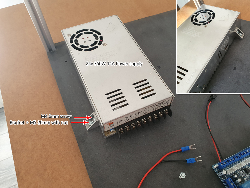
- 24V 350W power supply
- DM542 stepper drivers
- 5-axis breakout board
- Mushroom stop button 3-pin
- On / off power switch with built-in fuse
- Panel connectors / plugs
The guide below is for our previous model, it is built in the same way, except that the drive modules are positioned slightly differently.
For this guide, you need a 5-axis circuit board and some 4-wire cable and cable lugs. You can find the circuit board on our website or Amazon as an example. These cards are common and easy to obtain.
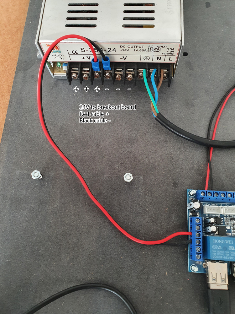
Connect 24v to the circuit board as shown, be careful with + and -. you don’t need to use cable lugs, you can screw the cables directly onto the terminals. You can use the 24-volt cable from your old board or run a new one from the power supply.
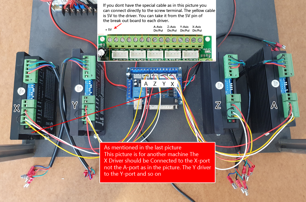
Then connect the signal cables already in the drive modules to the circuit board. We use a special cable that can be found on our website in the picture below. If you don’t do that, connect the cables to the terminals instead, (see small picture in picture). Please note that the picture below is of a different machine so the signal cables are wrong in the picture. Connect X drive module to X port Y to Y and so on…
The signal cables that were marked A in the previous picture are connected according to the small picture in the picture below.
We also need 5 volts for each drive module. This cable was marked X in the previous picture. Note that the 5-volt cable (the yellow one) also bridges to the terminal next to it. You can do the same but take 5 volts from the circuit board as per the small picture in the picture. You can bridge the 5-volt cable between each drive module or take a separate cable from the 5-volt port to each drive module.
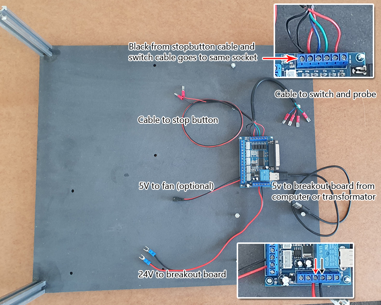
 Then plug in all the cables to your green connectors. The box below is for a different model, but the principle is the same. Connect according to the picture we asked you to take at the beginning of the beginning.
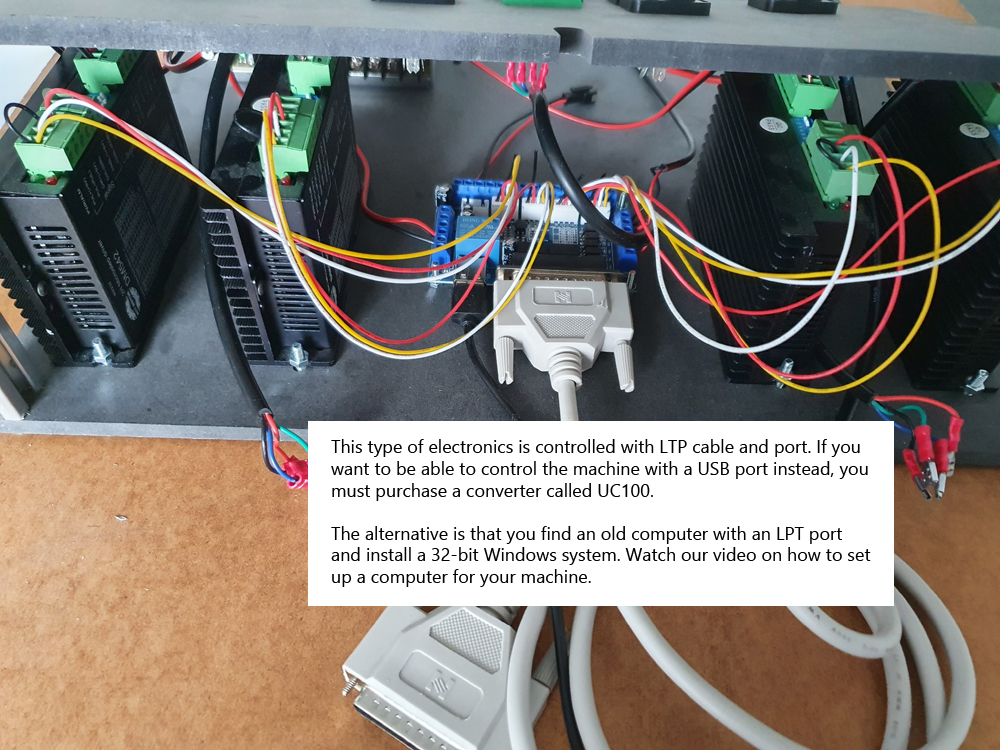
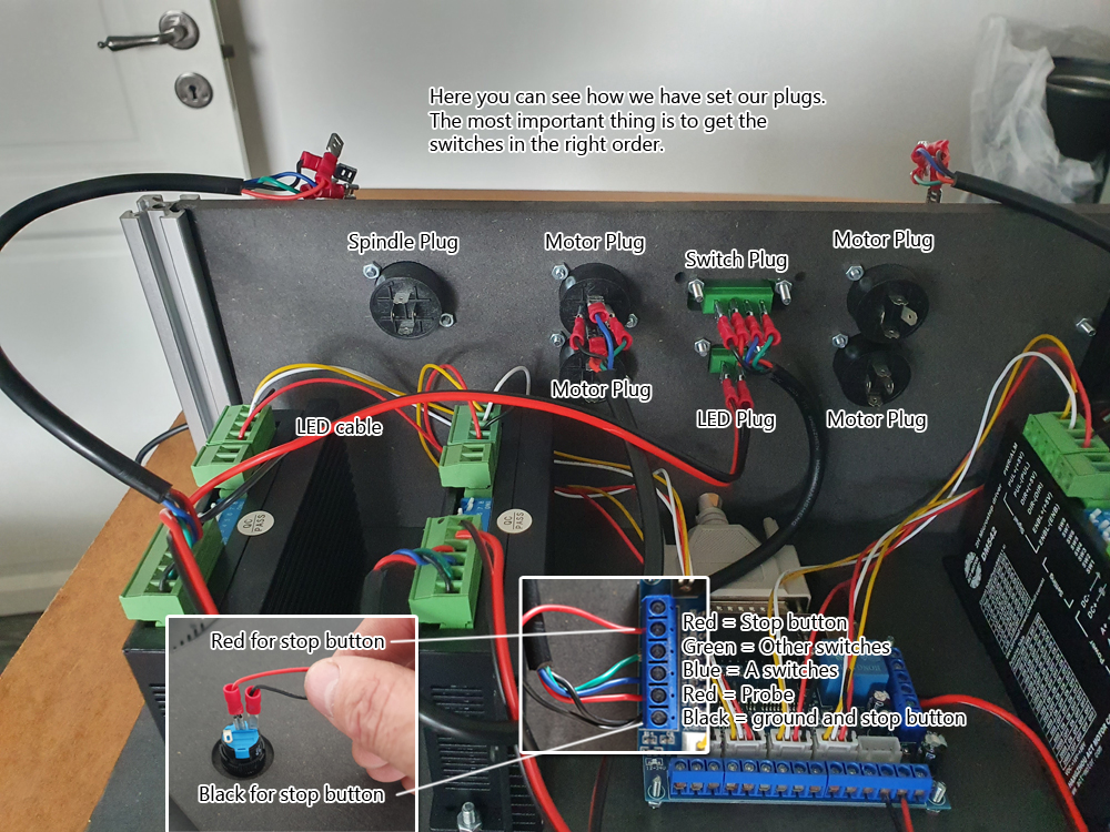 This electronics uses the LPT connector for control. Most industrial machines still use that port. You can use an old computer or a converter from LPT to USB called UC100. You can buy that module on our homepage. If you have an older computer with an LPT connector, you can watch the video in other guides on how to install it.


