This forum is still new and may look a bit empty at the moment.
Please don’t hesitate to ask your questions. If you are building a Raw Creative 2.5, planning your build or wondering about parts, setup or assembly, feel free to start a topic.
I will do my best to answer questions and help as much as I can. As more builders join, the forum will grow into a useful place for tips, build discussions and shared experience.
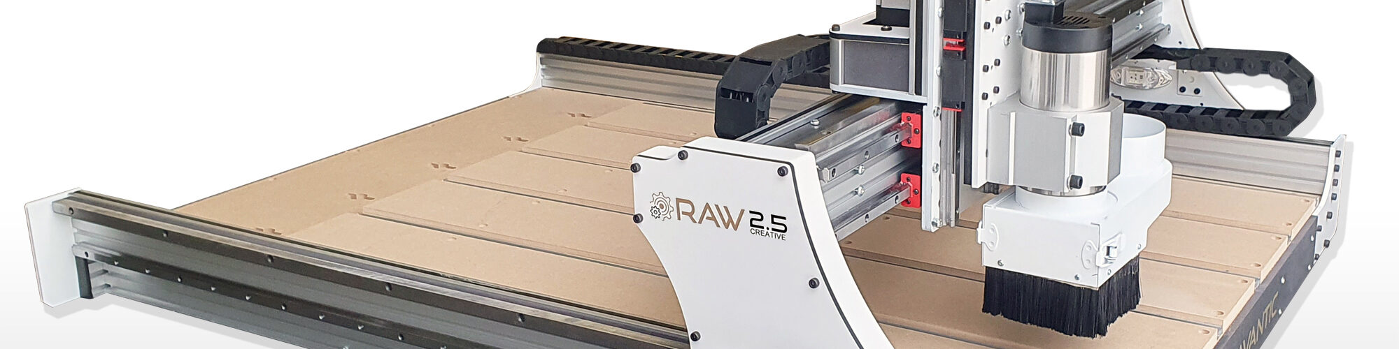
I am initially going to mount a standard handrouter on my machine. But both that one and the cnc I have today, which is much smaller, have ER11 collets, I am going to put a 2.2 kW spindle on it which is much stronger and has an ER20 collet (I think max tool diameter for ER11 is 6mm while for the ER20 it is 13mm).
Since the Z-axis (like X and Y) is direct-driven without a force reducing gearbox, I realize this spindle's weight may cause the Z axis to drop when the cnc is powered off.
I don't know what kind of brake system you use on the larger machines you build, but I am going to design an electronic brake that locks Z axis when the machine is powered off. This will keep the stepper locked, no matter if the machine is powered off manually or if power is lost due to power outage. This will protect tools and material.
I am considering tapping into the e-stop feature, so that the braking function works seamlessly with the other workings of the machine.
Any thoughts or considerations you think I better know before I start?
That is a very good point, and it is something worth thinking about when using a heavier spindle on the Z-axis.
On our larger machines we normally use a belt reduction on the Z-axis. Besides giving more torque and better resolution, the reduction also helps resist the Z-axis dropping when the power is off. It does not act as a true brake, but it adds mechanical resistance compared with direct drive.
For a direct-driven Z-axis with a heavier 2.2 kW spindle, the axis can drop when the motors are powered off, depending on the weight, screw/drive type, friction and how the Z-axis is built.
An electronic brake can be a good solution, but I would design it so it is fail-safe. In other words, the brake should be locked when power is off, and only release when the machine is powered and ready. That way it also works during a power outage.
I would also be careful with how it is connected to the E-stop. The brake should work together with the safety system, but it should not create a situation where the Z-axis is released during an emergency stop. Ideally, E-stop should stop motion and keep or apply the Z brake, not release it.
Another simple mechanical solution is to make a parking/rest position for the spindle. For example, a small support or stand where the Z-axis/spindle can rest when the machine is powered off. That is not as elegant as an automatic brake, but it is simple, reliable and avoids the spindle slowly dropping onto the workpiece or table.
So possible solutions are:
Belt reduction on Z-axis
Fail-safe electromagnetic brake
Gas spring or counterbalance
Mechanical parking support for the spindle
Parking the Z-axis at a safe height/location before powering off
For a DIY machine, I like simple and fail-safe solutions. A brake can be very good, but it should be tested carefully so it does not release at the wrong time or fight the motor during normal operation.
Thanks. Yeah, that is pretty much what I was thinking. Since I was not planning on any reduction of Z axis but to have direct drive, a passive electronic brake is probably easiest and also cheap.
A counterweight would be an easy solution but it would interfer with the cable chain. And since I am an electronics engineer, I see an electronic brake as an easy and appealing solution. To a hammer everything looks like a nail. 🙂
A passive electronic brake using the electromagnetic forces generated in the stepper motor itself under load cannot hold extensive weight. For that it would probably be better with a solenoid locking mechanism. But a 2.2kW spindle is probably just a little bit heavier than the 1.5kW spindle you use in one of your videos. Here are my design parameters:
* The brake must hold the weight without continuous power input
* The brake must automatically engage in case of power outage or e-brake action.
* The brake must protect the stepper driver from any surges caused by the stepper motor
* Visual indicators. Green light for disengaged brake (motor powered) and red for engaged brake (no power to motor).
* Since the brake must also engage on power loss, the circuit must be able to hold charge to power the red light for 45-60 seconds, enough so the operator can visually confirm it has engaged.
* I was thinking that I would design the circuit to handle 24-48V.
This will be a robust electromechanical solution using relays and a few electronic components to regulate and protect both the motor and the driver.
The working principle is that shorted coils on the stepper motor creates a mechanical resistance and makes it more difficult to turn the axle. It's probably not enough to hold very heavy spindles without any mechanical reduction but most likely enough to hold or at least slow the drop significantly. I will test this solution and design a circuitboard for it when I've proven the concept.
That sounds like a very interesting solution, and I think your thinking is right.
In practice, I do not think the brake needs to be extremely strong. With a 2.2 kW spindle mounted on the Z-axis, the weight is not that dramatic. On similar setups you can almost stop the Z-axis from dropping just by pinching the screw/shaft with your fingers, so it should not take a lot of braking force to hold it or at least slow it down enough to protect the tool and workpiece.
Your idea of using the stepper motor coils to create resistance is clever, especially since it is passive and can engage when power is lost. As you say, it may not be enough for a very heavy Z-axis, but for this type of setup it may work very well.
The most important things I would watch are exactly the points you mention: protecting the stepper driver, making sure the brake engages when power is lost or E-stop is active, and making sure the circuit never fights the driver when the machine is running normally.
I like the idea of red/green indicators too. That makes the system easy to understand for the operator.
Please share the result if you test it. It could be a very useful small add-on for the community, especially for users who want to run a heavier spindle on a direct-driven Z-axis.
I will certainly share all my findings. I beleive in contributing to this community. I was considering designing a cnc from ground up. But looking at your design I found it to be much more rigid than other diy cnc machines I've looked at.
So instead of going about it in my own solitude, I'd rather participate here, contribute with my now knowledge and experience where appropriate.
The electronic brakes relay cuts connection to the driver at the same time (actually just a few milliseconds before) it shorts motor coils. Since it's done by a single relay, no probable malfunction could cause shorting of the driver.
The driver/motor circuit, whether shorted or not, is galvanically separate from the rest of the electronics.